DIAGRAM Circuit Diagram 12v Power Supply Learn how to convert AC supply to DC supply with a regulated power supply circuit that includes a transformer, a rectifier, a filter, and a regulator. See the block diagram, characteristics, and examples of regulated power supply applications in mobile phones, oscillators, and amplifiers.

Learn how to build a simple power supply circuit that converts 220V or 110V AC to 5V DC using only 5 components. Follow the step-by-step tutorial with diagrams, parts list and tips. The power supply circuit diagram shows the various components and their connections that make up the power supply unit. It typically consists of a transformer, rectifier, voltage regulator, and filtering capacitors. Each component plays a crucial role in converting the incoming AC voltage from the mains into a regulated DC voltage that can be
Working, Circuit Diagram and ...
AC-DC power supply circuits are one of the most common circuit configurations in electronic systems. Though designs may vary, the task of converting AC power to DC power is vital in the functioning of a great many electronic devices. Examples of "split" or "dual" power supply schematic diagrams abound in textbooks. I'll let you do Learn how to design and build various power supply circuits for electronic projects. Find diagrams, explanations, and tips for linear and switching mode regulators, voltage boosters, and more. This is a schematic of a simple DC 12v 3A power supply circuit using 2N3055 transistor. This circuit can be very useful on the places where you want high current like 3A 12V to 4.5V, 6V & 9V Converter
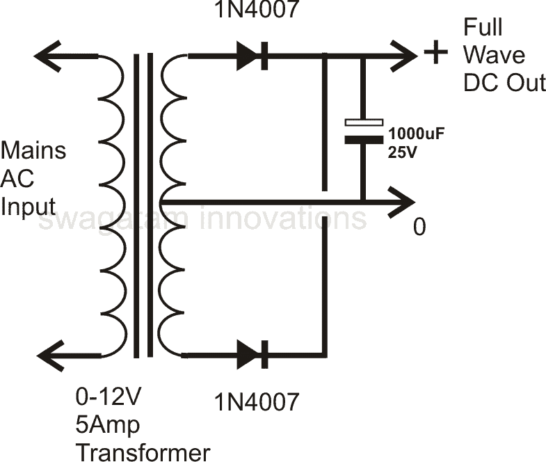
While a half wave rectifier is an option, its high power losses make a full wave rectifier or bridge rectifier a better choice for rectifying AC's full cycle. The figure below shows a full wave bridge rectifier. A bridge rectifier consists of four p-n junction diodes connected in the manner shown above. In the positive half cycle of the supply, the voltage induced across the secondary of the

PDF POWER SUPPLY DESIGN BASICS Circuit Diagram
A schematic diagram of a power supply is a simple visual representation of the power supply's components, connections, and its overall architecture. These diagrams can be helpful when troubleshooting, designing, or constructing a new power supply.

In this post I have explained how to design and build a simple power supply circuit right from the basic design to the reasonably sophisticated power supply. Hi sir Swagatam thanks for your very interesting circuit diagrams.I want to use the circuit - How to Get 9 V Variable Voltage from IC 7805 - in a way that to have suitable 5 to 12
