ESP8266 Tutorial Build An Automatic Plant Watering System Circuit Diagram Explore comprehensive documentation for the ESP8266-Based Air Quality Monitoring System with LCD Display and Wi-Fi Connectivity project, including components, wiring, and code. This project utilizes an ESP8266 NodeMCU to monitor air quality, temperature, humidity, and pressure using sensors like MQ135, DHT11, and BMP280. The data is displayed on a 16x2 I2C LCD and can be accessed remotely via
As concerns about air pollution grow globally, understanding and tracking air quality become paramount. This comprehensive guide will walk you through the step-by-step process of connecting the powerful SDS011 sensor with the versatile ESP8266, creating a cost-effective and efficient air quality monitoring system. An ESP8266 based air pollution detector is an easy and low cost way to create an air quality monitoring solution that is real time. In this comprehensive guide, we will go through step-by-step how to build a reliable air pollution detector using the ESP8266 Arduino NodeMCU and popular air quality sensors.

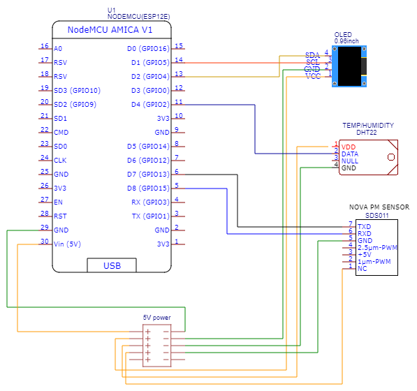
IoT Based Air Quality Index Monitoring with ESP8266 & MQ135 Circuit Diagram
MQ135 Air Quality Sensor. The MQ-135 gas sensor senses the gases like ammonia nitrogen, oxygen, alcohols, aromatic compounds, sulfide and smoke.The MQ-3 gas sensor has a lower conductivity to clean the air as a gas sensing material. In the atmosphere, we can find polluting gases, but the conductivity of the gas sensor increases as the concentration of polluting gas increases.
Overview. This is a simple prototype for an Environmental IoT Air Pollution/Quality Monitoring System for monitoring the concentrations of major air pollutant gases. The system uses 3 sensors like PMS5003 PM2.5 Particulate Matter Sensor, MQ-135 Air Quality Sensor, BME280 Barometric Pressure Sensor.In this IoT project, you can monitor the pollution level from anywhere using your computer or mobile.
Monitoring Circuit Diagram
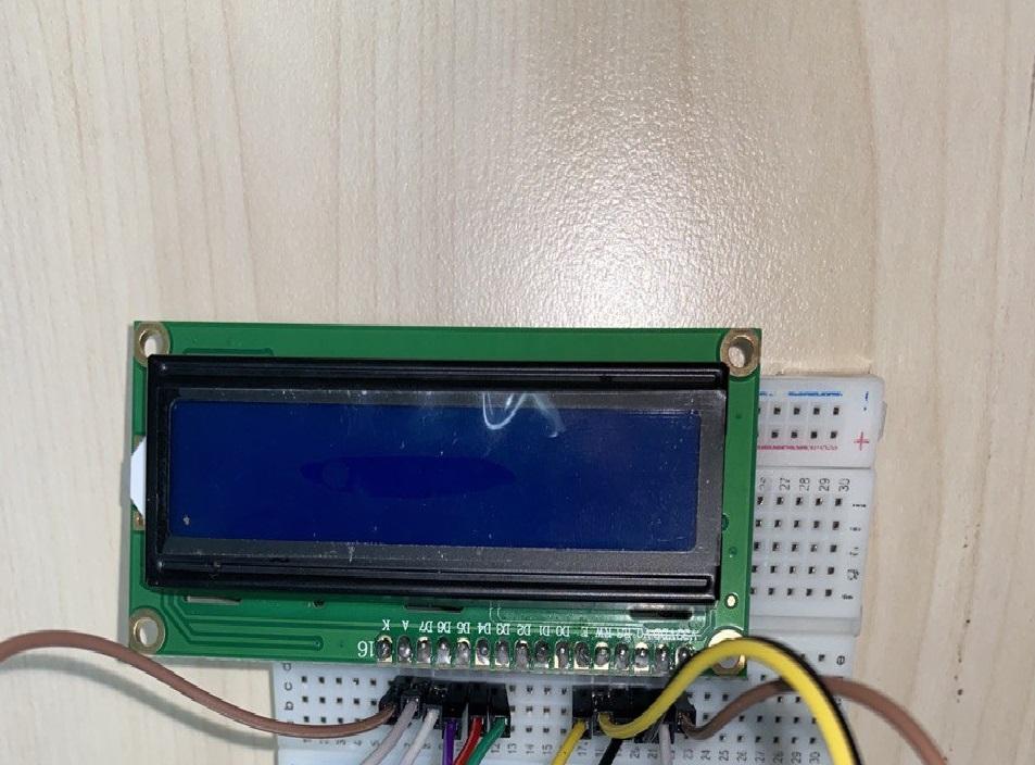
Testing and calibrating the sensor. The initial step involves calibrating the sensor. To achieve this, connect the sensor to the circuit and allow it to remain powered on for 24 hours to complete
